Machines
Compare Machines
Applications
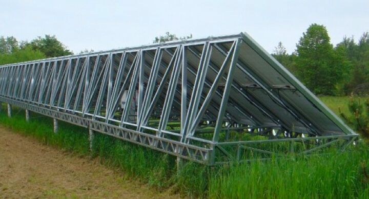
Frames, Trusses & Joists
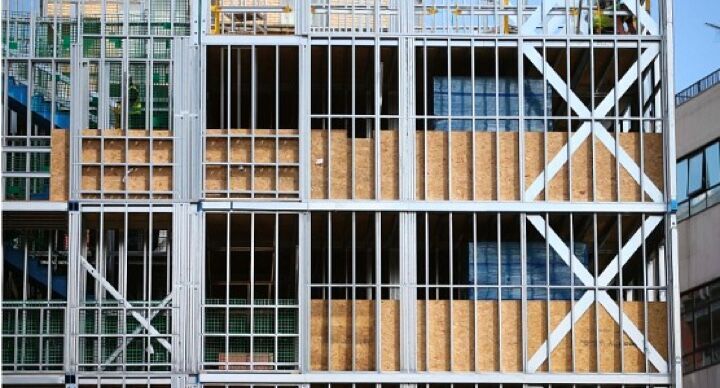
Commercial Construction
Rapid Building
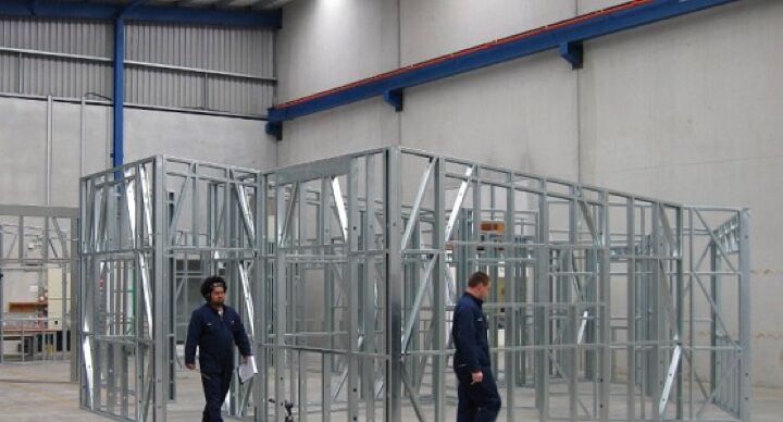
Modular Construction
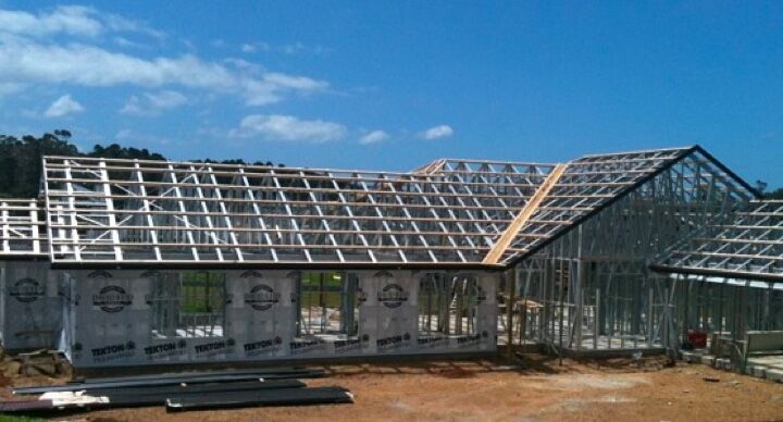
Roofing Systems
Custom Building